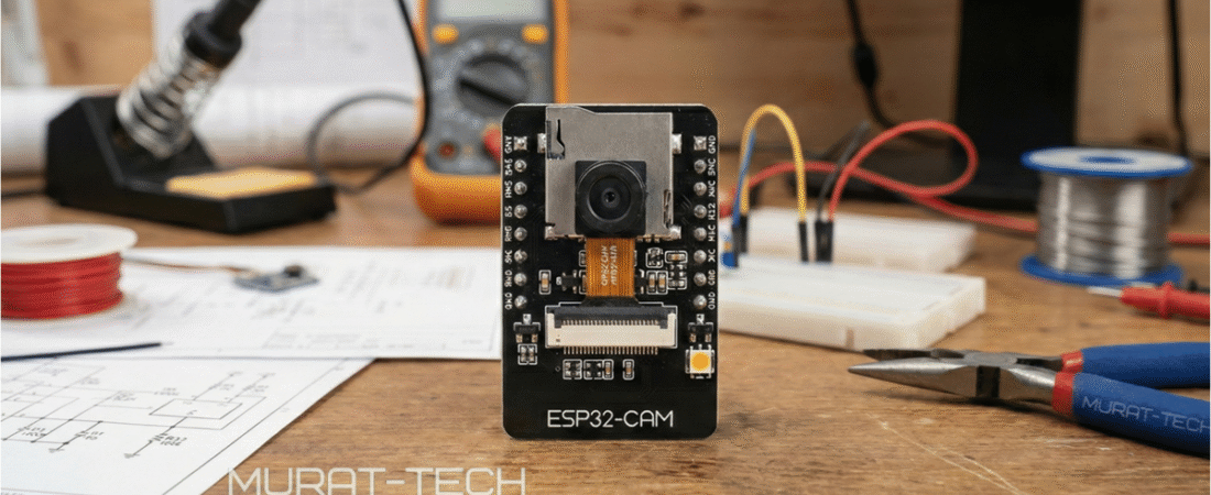
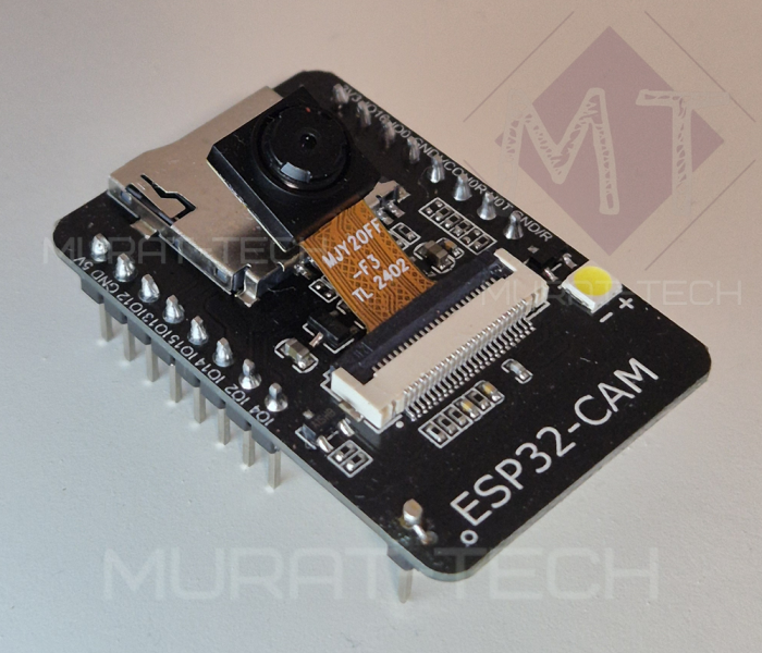
ESP32-CAM: More Pins
The ESP32-CAM has gained popularity among hobbyists and developers alike. One of its standout features is its ability to handle various applications, from IoT projects to surveillance systems. However, many users often find themselves limited by the number of available GPIOs (General Purpose Input/Output pins).
If you are searching for ESP32-CAM more pins to unlock the board’s full potential, this guide is for you.
By unlocking one pin and adding another through a simple board modification, you can create a full surveillance setup — for example, a PIR motion sensor plus a pan servo and a tilt servo (which can use the existing unlocked GPIO16) — all while keeping the SD-card slot fully functional.
But if you prefer non-destructive options, please check our guide with alternative solutions, especially if you lack basic electronics skills. Now, let’s dive deeper and safely unlock two additional pins for your projects.
This article will cover the following topics:
- Releasing GPIO4 on ESP32-CAM
- Releasing GPIO33 on ESP32-CAM
- Adding a New Header Pin for GPIO33
- Final Assembly: Soldering the GPIO33 Wire
- Conclusion
Releasing GPIO4 on ESP32-CAM
The first mod to show you here is how to release the GPIO4.
Unlike the software method, this approach fully frees GPIO4 and isolates it from the rest of the PCB. But if your project uses the micro-SD card, you will still need to enable 1-Bit Mode — check our tutorial here.
💡Good to know:
The resulting isolation prevents parasitic current draw that may cause unstable logic states, particularly when GPIO4 is used as an input—for instance, a sensor line might inadvertently trigger the Flash LED, leading to signal failure due to voltage drop.
This task is easily done by…
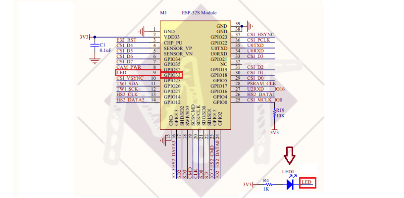
For a better understanding, please check the schematics below:
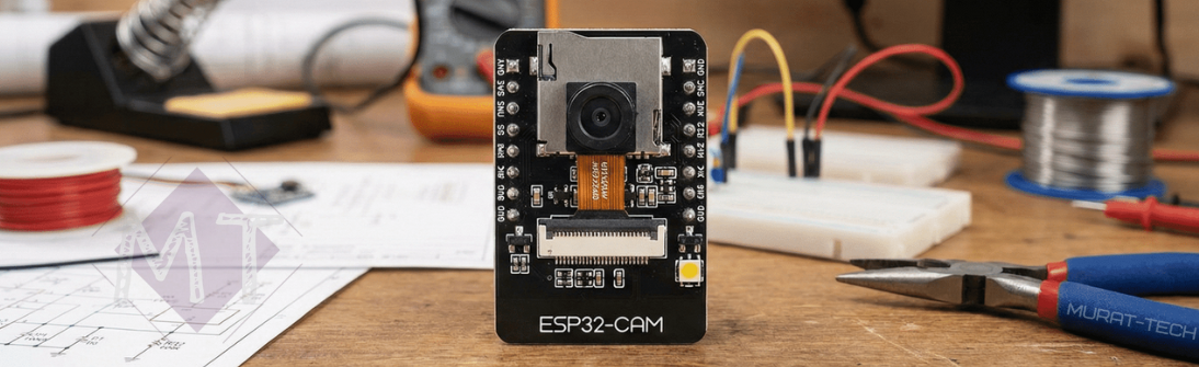
The next photos show where this resistor is, useful because ESP32-CAM PCBs often have no labels:

⚠️ Important:
Due to the existence of several manufacturers and counterfeit copies, your device may have a slightly different layout. Please take your time to check the PCB tracks against the schematics. This ensures you do not disconnect the wrong resistor.
Below is a board from another manufacturer, where…
Releasing GPIO33 on ESP32-CAM
Whereas GPIO4 is already accessible through the board’s existing pins, GPIO33 requires you to add your own physical header pin. This is because GPIO33 is internally assigned solely to the onboard LED (LED1 in the schematics below) and is not routed to the edge of the board.
Adding a New Header Pin for GPIO33
This is a straightforward task, but the most important thing is to be careful and patient. You will need to make slight modifications to your ESP32-CAM PCB…

The recommended location is shown in the image below. The alignment with the P2 header pins was preserved, and the standard 2.54 mm pitch was maintained, so if you use the same position, your modified ESP32-CAM will still fit on a breadboard:
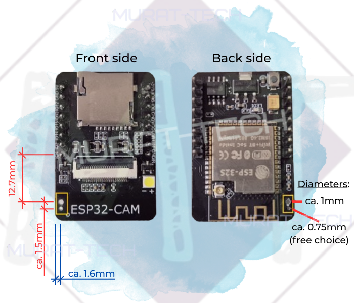
⚠️ Important:
The suggested location has no copper pad to solder the header pin to, you must fix it in place with appropriate glue (e.g., Cyanoacrylate/Super Glue). The second hole allows the wire to pass through the board, rather than wrapping around the PCB edge.
This results in a cleaner, more professional look.
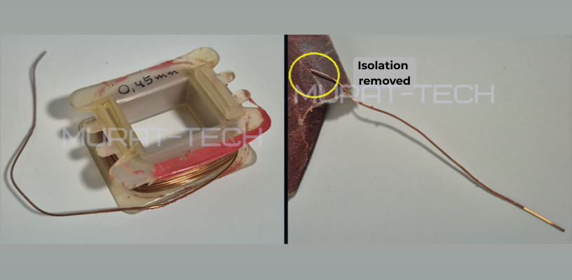
To make the connection, we recommend using enameled copper wire from the core of an old transformer. This wire is usually very thin (approx. 0.45mm), insulated with a varnish coating, malleable, and easy to solder. You can use any thin wire you have, but if you use enameled coil wire, remember to sand the tips before soldering to remove the insulation and ensure a proper electrical connection.
Final Assembly: Soldering the GPIO33 Wire
After removing the…
Top side of ESP32-CAM:
- Pass the wire through the hole near the new header pin.
- Solder the end of the wire to the header pin.
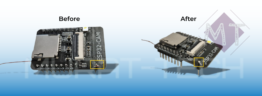
Botton side of ESP32-CAM:
That’s all! Your ESP32-CAM is now ready to use, but you will need to configure the new GPIOs in your code.
Not sure how to do it? Please check these software instructions!
Conclusion
By using hardware enhancements—such as multiplexers, I²C expanders, or direct pin-access modifications like the one demonstrated here—you can greatly expand what your projects can do. This even includes building a complete, standalone surveillance system — tutorial here.
This article serves as a foundation for expanding your knowledge of the ESP32-CAM and we invite you to share your own technical insights, questions, or experiences in the comments below!
Sharing what we learn and make is our passion. If you feel this effort is worth supporting, a small contribution helps sustain the creation of new tutorials and projects.
Support Us Here:
We appreciate your readership. See you in the next post!
ESP32-CAM: More Pins © 2025 by Murat-Tech Hub is licensed under CC BY-SA 4.0 ![]()
![]()
![]()